THz Broad-Band Phase Transformers
| Download THz Broad-band Phase Transformers Datasheet (PDF, 832 KB) |
THz monochromatic waveplates can be used only at single wavelength since phase retardation strongly depends on the wavelength. Sometimes it's necessary to have nearly constant retardation at the specified wavelength range. For that case we have developed THz broad-band phase transformers.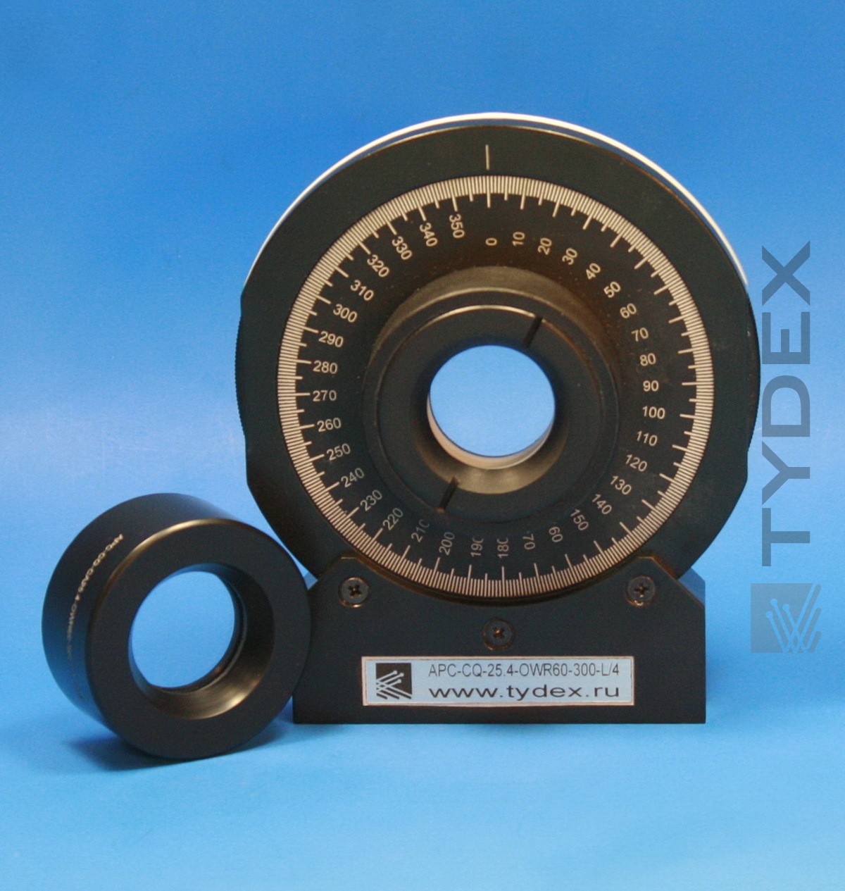
Basic methods of broad-band phase transformers calculation are well-known. However, they are not suitable for the case if measuring system has high resolution. So we have modified the methods to take into account interference effect. Broad-band phase transformers consist of several specially oriented crystal quartz plates. The plates are stacked together and fixed into a holder. According to Jones formalism system of several retardation plates is optically equal to system containing only two elements: so called “retarder” and “rotator” (please see Fig.1). Retarder provides required phase shift (usually π or π/2). Rotator turns the polarization plane at angle ω.
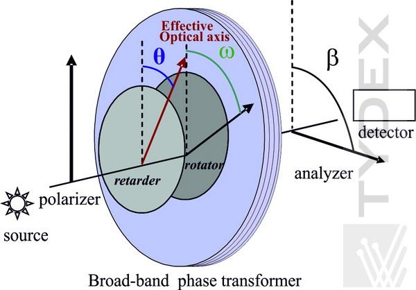
Fig. 1. Broad-band phase transformer in terms of Jones formalism and its position relative to polarizer and analyzer.
There are two types of broad-band phase transformers:
1) ω is not 0º and it depends on the wavelength. We call it “achromatic polarization converter” (APC). Example of ω behavior is below.
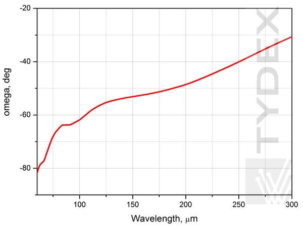
Fig. 2. a) Angle ω of the APC L/4@60-300 um.
2) ω is about 0º and it is constant within the operating wavelength range. In this case it is usual “achromatic waveplate” (AWP) and its operating principle is the same as of monochromatic waveplate.
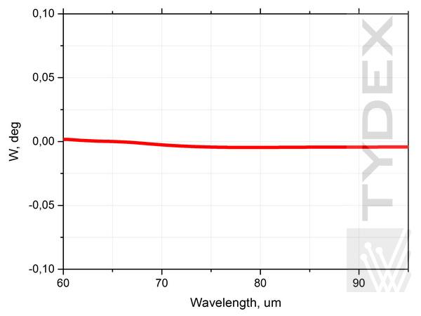
Fig. 2. b) Angle ω of the AWP L/4@60-95 um.
Currently quarter-wave achromatic polarization converter, quarter-wave and half-wave achromatic wave plates have been developed. There are some features of APC and AWP position relative to polarizer and analyzer (please see Fig.1). APC as well as AWP should be oriented to polarizer at angle θ (angle of effective optical axis of APC and AWP). Angle θ slightly depends on the wavelength (please see examples below). 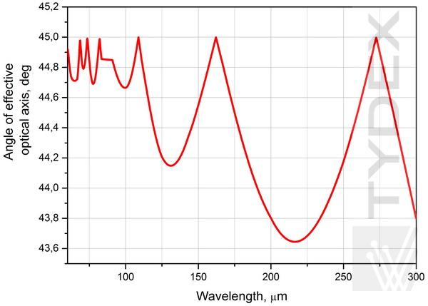
Fig. 3. a) Angle θ of effective optical axis of the APC L/4@60-300 um.
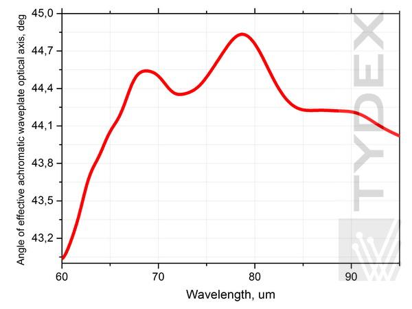
Fig. 3. b) Angle θ of effective optical axis of the AWP L/4@60-95 um.
Analyzer is oriented to polarizer axis at angle β (please see Fig. 1). In the case of AWP the analyzer position doesn’t depend on wavelength. However, if we deal with APC the analyzer should be adjusted according to:
1) ω(λ) dependence (please see Fig. 2 a)) if linear polarized radiation is transformed to circle polarized one;
2) β=ω(λ)±45º in the case of the transformation of circular polarization to linear one.
Negative sign of ω means that it’s necessary to rotate analyzer in opposite direction to θ, i.e. counterclockwise, if to look from the polarizer side.
Actually we are able to design L/4 APC, L/4 AWP, and L/2 AWP for sub-ranges within the wide interval from 60 um to 3000 um. Sub-ranges value depends on the concrete demands. One of determinative parameters is ellipticity tolerance (deviation of achieved circular polarization from ideal one). It can be +/-3%, +/-10% or another value specified by customer. Tolerance increasing will allow widening the operating ranges.
The APC L/4@60-300um and the AWP L/4@60-95um have been tested using the scheme shown at Fig.1. The APC and the AWP were situated relative to polarizer axis taking into account θ (λ) dependence (please see Fig.3a and 3b respectively). APC transmission spectra at different positions of analyzer have been measured using FTIR spectrometer Bruker Vertex 70 (please see Fig.4).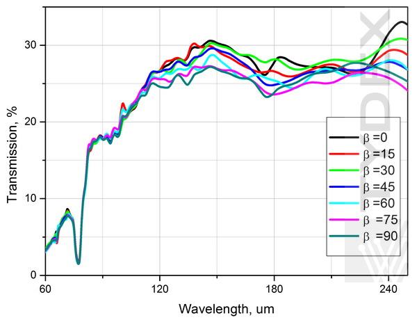
Fig. 4. Measured transmission spectra of the APC L/4@60-300 um at different analyzer positions.
We have chosen several wavelengths and made graph that shows dependence of APC transmission on analyzer angle for these wavelengths (please see Fig.5).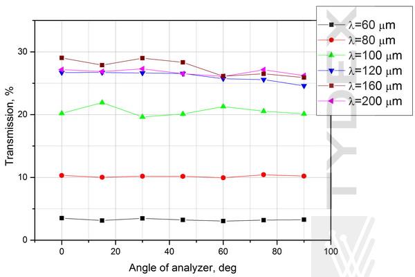
Fig. 5. Measured transmission of the APC L/4@60-300 um as a function of analyzer angle β.
As follows from the graph transmission doesn't depend on the angle (small data spread is due to features of our Fourier measurements). It means that radiation passed through the APC has circular polarization that confirms correct operation of the APC.
Optical properties of the AWP L/4@60-95um have been studied at 77um and 90um using high-power pulsed NH3 laser in Terahertz Center of University of Regensburg (Germany). Vertically polarized laser radiation as well as circle polarized one passing through the AWP was measured as a function of the rotation angle of analyzer. Typical measured signals are shown at Fig. 6. Deviations from ideal O-shape and 8-shape are no more 10%. The graphs confirm correct conversion of linear polarized radiation to circle polarized one and vice versa.
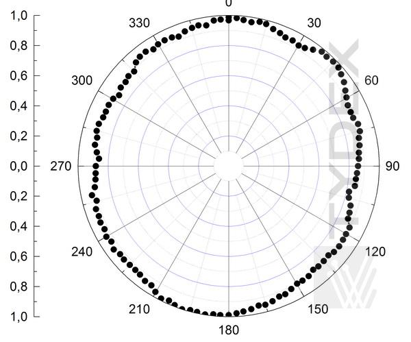
Fig. 6. a) Laser radiation intensity versus analyzer rotation angle in the case of linear polarized radiation passing through the AWPL/4@60-95um.
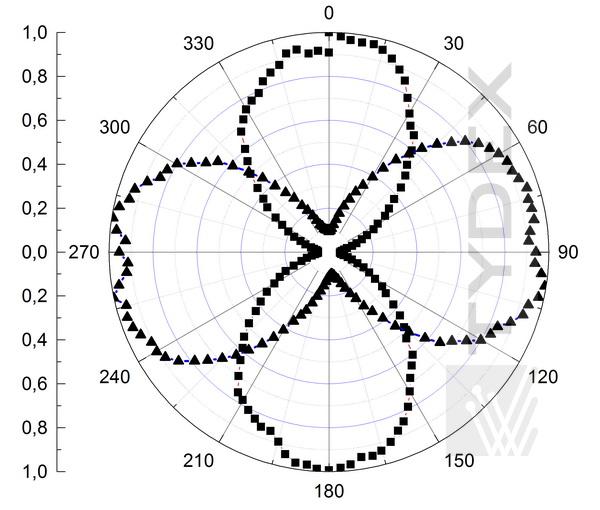
Fig. 6. b) Laser radiation intensity versus analyzer rotation angle in the case of circle polarized radiation passing through the AWPL/4@60-95um.
Common specification:
| THz Achromatic Polarization Converter |
THz Achromatic Wave Plate |
|
| Retardation | L/4 | L/4 |
| Operating wavelength range, um | 60-300 or specified by customer | 60-95 or specified by customer |
| Ellipticity tolerance, % | +/- 3 or specified by customer | +/- 10 or specified by customer |
| Clear apertura, mm | 25 (standard) or <25 (upon request) | 25 (standard) or <25 (upon request) |
| Holder | conventional optical component mount or rotator | conventional optical component mount or rotator |
Achromatic polarization converters as well as achromatic wave plates are manufactured upon request.
Please specify frequency resolution of your measuring system and type of polarization conversion (linear polarization should be changed to circular one or vice versa) in your RFQ.
For price quotation and delivery please fill in our request form.
Optics is ready to be shipped!
Optics Stock
Shipment/ Payment/ Warranty ...


